10.13.1 Purpose
Data flow diagrams show where data comes from, which activities process the data, and if the output results are stored or utilized by another activity or external entity.
10.13.2 Description
Data flow diagrams portray the transformation of data. They are useful for depicting a transaction-based system and illustrating the boundaries of a physical, logical, or manual system.
A data flow diagram illustrates the movement and transformation of data between externals (entities) and processes. The output from one external or process is the input to another. The data flow diagram also illustrates the temporary or permanent repositories (referred to as data stores or terminators) where data is stored within a system or an organization. The data defined should be described in a data dictionary (see Data Dictionary (p. 247)).
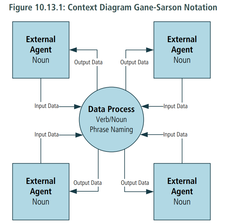
Data flow diagrams can consist of multiple layers of abstraction. The highest level diagram is a context diagram which represents the entire system. Context diagrams show the system in its entirety, as a transformation engine with externals as the source or consumer of data

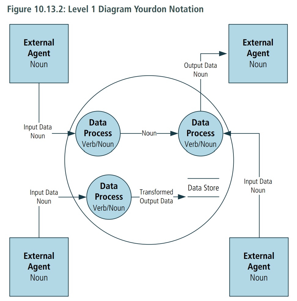
The next level of data flow diagrams is the level 1 diagram. Level 1 diagrams illustrate the processes related to the system with the respective input data, output transformed data, and data stores.

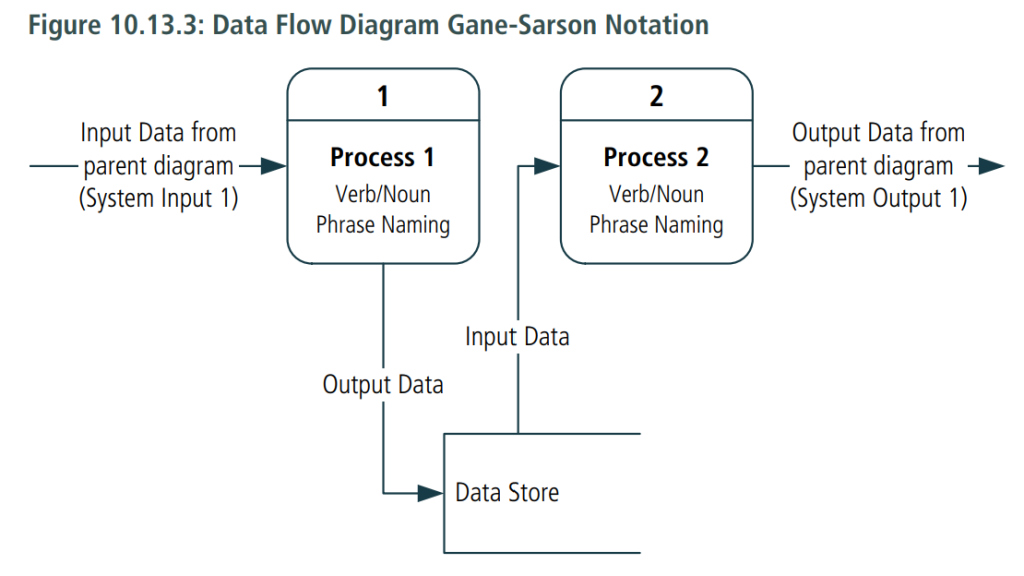
Further levels of the data flow diagram (level 2, level 3 and so forth) break down the major processes from the level 1 diagram. Level 1 diagrams are useful to show the internal partitioning of the work and the data that flows between the partitions, as well as the stored data used by each of the partitions. Each of the partitions can be further decomposed if needed. The externals remain the same and additional flows and stores are defined.
Logical data flow diagrams represent the future or essential state – that is, what transformations need to occur regardless of the current physical limitations.
Physical data flow diagrams model all of the data stores, printers, forms, devices, and other manifestations of data. The physical diagram can show either the current state or how it will be implemented.
10.13.3 Elements
.1 Externals (Entity, Source, Sink)
An external (entity, source, sink) is a person, organization, automated system, or any device capable of producing data or receiving data. An external is an object which is outside of the system under analysis. Externals are the sources and/or destinations (sinks) of the data. Each external must have at least one data flow going to or coming from it. Externals are represented by using a noun inside a rectangle and are found within context-level diagrams as well as lower levels of abstraction.
.2 Data Store
A data store is a collection of data where data may be read repeatedly and where it can be stored for future use. In essence, it is data at rest. Each data store must have at least one data flow going to or coming from it. A data store is represented as either two parallel lines or as an open-ended rectangle with a label.
.3 Process
A process can be a manual or automated activity performed for a business reason. A process transforms the data into an output. Naming standards for a process should contain a verb and a noun. Each process must have at least one data flow going to it and one data flow coming from it. A data process is represented as a circle or rectangle with rounded corners.
.4 Data Flow
The movement of data between an external, a process, and a data store is represented by data flows. The data flows hold processes together. Every data flow will connect to or from a process (transformation of the data). Data flows show the inputs and outputs of each process. Every process transforms an input into an output. Data flows are represented as a line with an arrow displayed between processes. The data flow is named using a noun.


10.13.4 Usage Considerations
.1 Strengths
- May be used as a discovery technique for processes and data or as a Technique for the verification of functional decompositions or data models.
- Are excellent ways to define the scope of a system and all of the systems, interfaces, and user interfaces that attach to it. Allows for estimation of the effort needed to study the work.
- Most users find these data flow diagrams relatively easy to understand.
- Helps to identify duplicated data elements or misapplied data elements.
- Illustrates connections to other systems.
- Helps define the boundaries of a system.
- Can be used as part of system documentation.
- Helps to explain the logic behind the data flow within a system.
.2 Limitations
- Using data flow diagrams for large-scale systems can become complex and difficult for stakeholders to understand.
- Different methods of notation with different symbols could create challenges pertaining to documentation.
- Does not illustrate a sequence of activities.
- Data transformations (processes) say little about the process or stakeholder.
